Taming the T-handle

Academic textbooks are silent about T-handles making spectacular somersaults in space, with no forces acting, except of the old fashioned and mysterious “force of inertia”. And why is it so? My answer is simple: because of inadequate education. Inadequately trained are physicists and mathematicians. Therefore, of course, engineers as well. Not just inadequately educated. Lazy they are as well. Since they can learn from the available sources. But they do not want. They prefer going the parties and pubs, and watching movies. Learning about elliptic functions is too much of a trouble for them. It was not so some one hundred years ago. But it is very bad now, when what counts in science are “impact factor points” rather than knowledge. Papers are written nowadays not in order to share research results. They are written for providing “impact factor points”.

“The impact factor (IF) is a measure of the frequency with which the average article in a journal has been cited in a particular year. It is used to measure the importance or rank of a journal by calculating the times it’s articles are cited.”

10 simple strategies to increase the impact factor of your publication
“Impact factors are heavily criticized as measures of scientific quality. However, they still dominate every discussion about scientific excellence. They are still used to select candidates for positions as PhD student, postdoc and academic staff, to promote professors and to select grant proposals for funding. As a consequence, researchers tend to adapt their publication strategy to avoid negative impact on their careers. Until alternative methods to measure excellence are established, young researchers have to learn the “rules of the game”.”

The effect we are discussing, the so called Dzhanibekov effect, has been discovered by chance by the Russian cosmonaut and scientist V. A. Dzhanibekov in 1985.

The discovery apparently has been kept in secrecy for 10 years. But I think that the Americans have learned about this “secret” almost immediately and they charged their scientists, experts in gravity effects, with the task of checking if the effect is important for the Defense of the Country.

The Invention Secrecy Act of 1951 (Pub.L. 82–256, 66 Stat. 3, enacted February 1, 1952, codified at 35 U.S.C. §§ 181–188) is a body of United States federal law designed to prevent disclosure of new inventions and technologies that, in the opinion of selected federal agencies, present a possible threat to the national security of the United States.

I think that the experts quickly came to the conclusion that they do not see anything of a practical value here, there are no national security threats from nuts freely flipping in space, and therefore they decided to let the mathematicians to publish a paper on the subject:

Mark S. Ashbaugh, Carmen C. Chicone and Richard H. Cushman, “The Twisting Tennis Racket“. Journal of Dynamics and Differential Equations. 3 (1): 67–85 (1991)

Two of the authors, Aschbaugh and Chicone, were mathematicians from the University of Missouri, the third one, Cushman, a mathematician from Utrecht. They wrote in their paper that W. Burke from the University of California at Santa Cruz has shown to Cushman the effect. The effect they described consisted of:

The classical treatments of the dynamics of a tennis racket about its intermediate axis fail to describe a remarkable aspect of its motion which is revealed in the following experiment. Mark the faces of the racket so that they can be distinguished. Call one rough and the other smooth. Hold the racket horizontally by its handle with the smooth face up. Toss the racket into the air attempting to make it rotate about the intermediate axis (namely, the axis in the plane of the face which is perpendicular to the handle). After one rotation, catch the racket by the handle. The rough face will almost always be up! In other words, the racket typically makes a half-
twist about its handle.

It is rather lame when compared to the effect with a flipping T-handle that has been observed in space:

Burke was a physicist working on gravity. The three mathematicians together managed to conclude that strange behavior is to be expected. But they were not able to solve the problem completely. Cushmann tried to solve the problem later on. In 2000 he has published a set of lectures entitled “No polar coordinates“, where he admitted: “I am not a master of Weierstrass’ theory of elliptic functions, so I won’t do this integral. But Whittaker [42] is and he does it.” Strange, a mathematician, and he does not know how to integrate, and does not even want to know.

But we want to know, we want to tame the flipping T-handle. Domesticated, tamed animals are useful.

In the last post, Standing on the shoulders of giants, I used the ideas from the paper by Ramses van Zon, Jeremy Schofield, “Numerical implementation of the exact dynamics of free rigid bodies“, J. Comput. Phys. 225, 145-164 (2007), and we came to the point where we have represented the attitude matrix Q(t) as the product:

(1)   \begin{equation*}Q(t)=Q_1(t)Q_0(t),\end{equation*}

where

(2)   \begin{equation*}Q_1(t)=\begin{bmatrix}\cos\psi(t)&-\sin\psi(t)&0\\\sin\psi(t)&\cos\psi(t)&0\\0&0&1\end{bmatrix},\end{equation*}

(3)   \begin{equation*}Q_0(t)=\begin{bmatrix}\frac{L_1(t)L_3(t)}{LL_p(t)}&\frac{L_2(t)L_3(t)}{LL_p(t)}&-\frac{L_p(t)}{L}\\-\frac{L_2(t)}{L_p(t)}&\frac{L_1(t)}{L_p(t)}&0\\\frac{L_1(t)}{L}&\frac{L_2(t)}{L}&\frac{L_3(t)}{L}\end{bmatrix},\end{equation*}

(4)   \begin{equation*} L_p(t)=\sqrt{L_1(t)^2+L_2(t)^2},\end{equation*}

(5)   \begin{equation*} L=\sqrt{L_1(t)^2+L_2(t)^2+L_3(t)^2},\end{equation*}

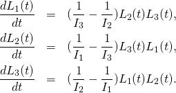
and \vec{L}(t)=(L_1(t),L_2(t),L_3(t)) is the solution of the Euler equations (this time we write them in terms of angular momentum rather than angular velocity):

(6)   \begin{eqnarray*} \frac{dL_1(t)}{dt}&=&(\frac{1}{I_3}-\frac{1}{I_2})L_2(t)L_3(t),\\ \frac{dL_2(t)}{dt}&=&(\frac{1}{I_1}-\frac{1}{I_3})L_3(t)L_1(t),\\ \frac{dL_3(t)}{dt}&=&(\frac{1}{I_2}-\frac{1}{I_1})L_1(t)L_2(t). \end{eqnarray*}
The task is now to derive the differential equation for \psi(t) knowing that Q(t) satisfies the equation

(7)   \begin{equation*}\frac{dQ(t)}{dt}=Q(t)W(t),\end{equation*}

where

    \[W(t)=\begin{bmatrix}0&-\Omega_3(t)&\Omega_2(t)\\\Omega_3(t)&0&-\Omega_1(t)\\-\Omega_2(t)&\Omega_1(t)&0\end{bmatrix}=\begin{bmatrix}0&-\frac{L_3(t)}{I_3}&\frac{L_2(t)}{I_2}\\\frac{L_3(t)}{I_3}&0&-\frac{L_1(t)}{I_1}\\-\frac{L_2(t)}{I_2}&\frac{L_1(t)}{I_1}&0\end{bmatrix}.\]

Getting the differential equation for \psi(t) is now a purely mechanical task. Therefore I will simply show the end result, and then show the REDUCE code that verifies this result. The result is:

(8)   \begin{equation*}\frac{d\psi(t)}{dt}=L\frac{L_1(t)^2I_2+L_2(t)^2I_1}{I_1I_2(L_1(t)^2+L_2(t)^2)}.\end{equation*}

And here is the REDUCE code. It has two parts. Here we use the first part, but at the end of this post we are also using the second part:


OPERATOR Q0,Q1,W,psi,L1,L2,L3,L,Lp;
Lp(t):=sqrt(L1(t)**2+L2(t)**2);
% L:=sqrt(L1(t)**2+L2(t)**2+L3(t)**2);
Q0:=MAT(
(L1(t)*L3(t)/(L*Lp(t)),L2(t)*L3(t)/(L*Lp(t)),-Lp(t)/L),
(-L2(t)/Lp(t),L1(t)/Lp(t),0),
(L1(t)/L,L2(t)/L,L3(t)/L));
Q1:=MAT((cos(psi(t)),-sin(psi(t)),0),(sin(psi(t)),cos(psi(t)),0),(0,0,1));
W:=MAT( (0,-L3(t)/I3,L2(t)/I2),(L3(t)/I3,0,-L1(t)/I1),(-L2(t)/I2,L1(t)/I1,0));
FOR ALL t LET L3(t)**2=L**2-L1(t)**2-L2(t)**2;
FOR ALL X LET COS X**2=1-(SIN X)**2;
FOR ALL t let
DF(L1(t),t)=(1/I3-1/I2)*L2(t)*L3(t),
DF(L2(t),t)=(1/I1-1/I3)*L3(t)*L1(t),
DF(L3(t),t)=(1/I2-1/I1)*L1(t)*L2(t);
Q:=Q1*Q0;
eq1:=(Q1*Q0*W-Q1*DF(Q0,t))*Tp(Q0);
% Here we get the same d psi/dt from four entries of the matrix
dpsi1:=eq1(1,1)/(-sin(psi(t)));
dpsi2:=eq1(1,2)/(-cos(psi(t)));
dpsi3:=eq1(2,1)/(cos(psi(t)));
dpsi4:=eq1(2,2)/(-sin(psi(t)));
Q1*Q0*MAT((L1(t)),(L2(t)),(L3(t)));
FOR ALL t LET DF(psi(t),t)=dpsi1;
%And here we check that we have the right equation:
DF(Q,t)-Q*W;
% This is the second part, where we substitute expressions for L1,L2,L3 and verify
A1:=L*sqrt(I1*(d*I3-1)/(I3-I1));
A2:=L*sqrt(I2*(d*I3-1)/(I3-I2));
A3:=L*sqrt(I3*(1 - d*I1)/(I3 - I1));
L1(t):=A1*cn(t);
L2(t):=A2*sn(t);
L3(t):=A3*dn(t);
FOR ALL t LET cn(t)^2=1-sn(t)^2;
dpsi1;
c1:=1/I3;
c2:=1/I1-1/I3;
C3:=(I3*(I2-I1))/(I1*(I3-I2));
dpsi1-L*(c1+c2/(1+c3*sn(t)^2));
END;

Next thing is to use our formulas for the solutions of the Euler equations (L_1(t),L_2(t),L_3(t)) – see Solving Euler’s equations. Here we adapt these formulas so that they give the solution for \vec{L} rather than for \vec{\Omega}:

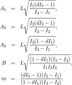
(9)   \begin{eqnarray*} L_1(t)&=&A_1\,\cn(Bt,m),\\ L_2(t)&=&A_2\,\sn(Bt,m),\\ L_3(t)&=&A_3\,\dn(Bt,m),\\ \end{eqnarray*}

(10)   \begin{eqnarray*} A_1&=&L \sqrt{\frac{I_1(dI_3-1)}{I_3-I_1}},\\ A_2&=&L\sqrt{\frac{I_2(dI_3-1)}{I_3-I_2}},\\ A_3&=&L \sqrt{\frac{I_3(1-dI_1)}{I_3-I_1}},\\ B&=&L\sqrt{\frac{(1-dI_1)(I_3-I_2)}{I_1I_2I_3}},\\ m&=&\frac{(dI_3-1)(I_2-I_1)}{(1-dI_1)(I_3-I_2)}. \end{eqnarray*}

That is another purely mechanical task. Therefore again I give the result and show the REDUCE code verifying it.

(11)   \begin{equation*}\frac{d\psi(t)}{dt}=L\left(c_1+\frac{c_2}{1+c_3\,\sn^2(Bt,m)}\right),\end{equation*}

where

(12)   \begin{equation*}c_1=\frac{1}{I_3},\quad c_2=\frac{1}{I_1}-\frac{1}{I_3},\quad c_3=\frac{I_3(I_2-I_1)}{I_1(I_3-I_2)}.\end{equation*}

We have differential equation for \psi. We need to solve it. Van Zon and Schofield as it seems got tired towards the end of their paper and they did give us a nice formula. We will get such a nice formula in the next post.

1, 2, 3 and butterfly effect

I know: my blog is somewhat chaotic. But what is chaos? From Celestial Mechanics: The Waltz of the Planets” by Alessandra Celletti and Ettore Perozzi:


Chaos From the Greek Χάος, denoting primordial emptiness. The term is used to indicate the extreme sensitivity of a trajectory to the initial conditions, which implies unpredictable dynamical behaviour in the corresponding dynamical system.

With T-handle floating in space and flipping for no apparent reason – it looks like we are in a chaotic mode:

But are we? Where is “the extreme sensitivity of a trajectory to the initial conditions“? We have to address this question. The waltz of planets can be, in some respect, chaotic. But sometimes it is well organized. Like this waltz:

1,2,3 and 1,2,3, and my T-handle that replicates the cosmic behavior in the Dzhanibekov effect (see my previous posts) has principal moments of inertia 1,2,3. Why? What 1,2,3 has to do with chaos?

Time to explain. In general, when moons and planet spin, their motion is not chaotic. But sometimes it can be. Let us take my T-handle with principal moments of inertia I_1=1,I_2=2,I_3=3 (see my previous post).

Spin it about its shorter axis. It may show the strange flipping behavior – see the animated gif below (click to open it)

The “extreme sensitivity of a trajectory to the initial conditions” happens when the parameter d, that is the ratio of the doubled kinetic energy to squared angular momentum vector, is close to 1/I_2. The motion is governed by Jacobi elliptic functions \cn,\sn,\dn. The period \tau of these functions directly affects the time spent by the T-handle between flips. And this period is a very sensitive function of d, when d is close to 1/I_2.
Here is the graph of \tau for our T-handle:

The formula for \tau(d) involves elliptic K function. But for d very close to 1/I_2 there is an approximate (asymptotic) formula derived in the paper “Janibekov’s effect and the laws of mechanics” by A.G. Petrov and S. E. Volodin, Doklady Physics}, 58(8):349–353, 2013:

    \[\tau_0(d)=2\log\frac{16}{|\mu|},\]

where

    \[\mu=\frac{I_2(1-d I_2)(I_3-I_1)}{(I_3-I_2)(I_2-I_1)}.\]

Here is how the two formulas compare:

The blue curve is the simple asymptotic formula.

But why 1,2,3?

Why? Because 1,2,3 is optimal. But what is optimal?

How do we know if 9 to 5 is the most optimal time to work? – Quora
We don’t and we never will know, because everyone is different.

So, what did I optimize to get my 1,2,3? First I had a vague feeling that this is good

Genesis 1:31 God saw all that he had made, and it was very good …

But then I was able to prove that it was good by optimizing \tau(d). The dimensionless parameter \epsilon=1-d I_2 tells us how close we are to the critical value of d=1/I_2. Being very close, near the peak in the graphs above, we want to know what should be the values of I_1,I_2,I_3 for which the period \tau is maximal? We use the approximate formula above. To find where is the maximum of \tau, with \epsilon fixed, is to find where is the minimum of the ratio:

    \[\frac{I_2(I_3-I_1)}{(I_3-I_2)(I_2-I_1)}.\]

Here I_1,I_2,I_3 cannot be completely arbitrary. The moments of inertia should satisfy the inequality I_1+I_2\geq I_3. Suppose I_2=2. What should be I_1,I_2? I used Mathematica to get the answer:

If I assume that I_2=2, then I_1=1,I_3=3. If I assume that I_2=20, then I_1=10,I_3=30. Simple?

So, even if everyone is different, even if there is no optimal answer that would satisfy everybody, there is an optimal answer to my needs, and that is 1,2,3.

“In trying to please all, he had pleased none.”
― Aesop, Aesop’s Fables

With 1,2,3 we have more time to see the butterfly flying. By flipping its wings it can change dramatically the period of the flying T-handle on the other side of the planet.

Dzhanibekov effect – handling the T-handle

Errors that you remember most are the errors you have made yourself. Toys that you remember most are the toys that you have made yourself. As a kid I was making all kind of toys. Planes that would fly. Slings that would shoot. But also this funny toy that I was not able to find on Youtube in English. I found it only in Polish. Here it is – the “worm”:

And here are more detailed instructions with narration in Polish, but it should not matter, because you see all the details:

The bearing ball inside, invisible, makes it to behave strangely, the “worm” flips and jumps, almost like being alive.
So much about kid’s toys. Now we are playing with another toy, that also looks like being alive. Except that it whirls and flips in space, on ISS space station:

Dzhanibekov effect is the name. It does not have a bearing ball inside. What is hidden inside are Jacobi elliptic functions. They make it to flip, for no apparent reason at all, and do it, as it seems, periodically. Why? Dzhanibekov, the Russian cosmonaut who has discovered the effect, didn’t know why. He wrote to me that it is still a puzzle for him, though he prefers now to concentrate on “quantum puzzles”.
The movie above shows a T-handle. So, in today’s post I will construct my own T-handle that will whirl and flip the same way, but without going to space. We will do it with graphics, with math, with numbers.

I want to build a T-handle with principal moments of inertia 1,2,3 (I like this sequence). It will look like this:

But I want to make it as simple as possible, so I will make it very-very thin. Mathematically: I will make it of lines rather than tubes:

One line is along the x-axes. I fix it to have length L_1=2, from x=-1, to +1. For the metal I choose the linear density to be \mu=3. So the mass of the horizontal tube is 6. The length of the vertical part is to be found. I want it to be such that the principal moments of inertia with respect to the center of mass are 1,2,3.

First we need to find the formula for the center of mass position y. It is clear, from symmetry, that the center of mass will have x-coordinate zero. We need a formula for y. The center of mass of the horizontal part, that has mass m_1=6, is at (0,0). The center of mass of the vertical part, which has mass 3L_2, is at (0,L_2/2). Thus the y coordinate of the center of mass of our T-handle is

    \[y=\frac{m_1\times 0 + m_2\times L_2/2}{m_1+m_2}=\frac{3L_2^2/2}{6+3L_2}= \frac{L_2^2}{4+2L_2}.\]

Now we need to calculate the moments of inertia. First the moment of inertia with respect to the y-axis.
Wikipedia has a List of moments of inertia. There we find that for a cylinder of length L and mass m the moment of inertia with respect to the axis through its center is mL^2/12. I checked, calculating it myself, and it is correct. Here is how you can calculate it:

    \[I=2\int_0^{L/2}x^2\mu dx=2\mu\frac{x^3}{3}|_{L/2}=2\mu\frac{L^3}{3\times 8}=m\frac{L^2}{12}.\]

In our case only L_1 contributes to the moment of inertia with respect to the y-axis, because we assume our cylinders to be of zero diameter. And the contribution from L_1 is 6\frac{2^2}{12}=2. This is our I_2:

    \[I_2=2.\]

Our task is now to choose the Length L_2 so that the moment of inertia I_1 of the whole body with respect to the horizontal axis through y is 1.
It will be convenient to use what is called “Parallel axis theorem“. From Wikipedia:

First consider the contribution from L_1. The mass is m_1=6, the distance is d=y, so the contribution is

    \[I_{1,1}=0+6y^2.\]

The first term here is 0 since the moment of inertia of L_1 with respect to the x-axis is zero.
Then the contribution from L_2:

    \[I_{1,2}=\mu L_2 \frac{L_2^2}{12}+\mu L_2(L_2/2-y)^2.\]

Substituting the expression for y, after some little calculation, we get

    \[I_1=I_{1,1}+\[I_{1,2}=\frac{L_2^3(8+L_2)}{4(2+L_2)}.\]

We now solve the equation L_2=1. This is fourth degree equation, we find that two roots are real, and only one is positive:

    \[L_2=1.10938.\]

This is our T-handle.
And here is the animation – with Jacobi elliptic functions inside. The T-handle is flipping, as if being alive, with elliptic functions inside:

Click on the image to open the gif animation.